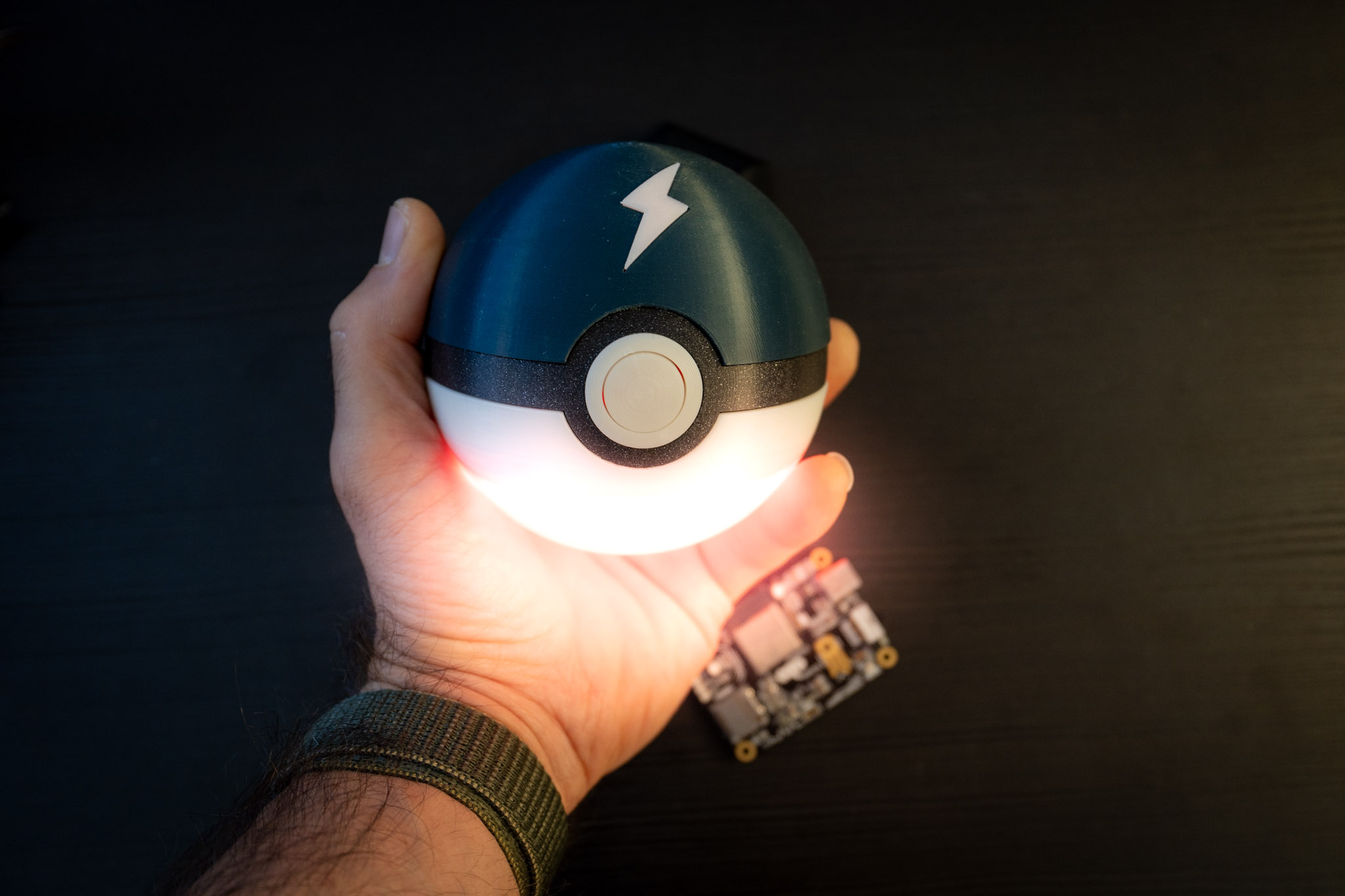
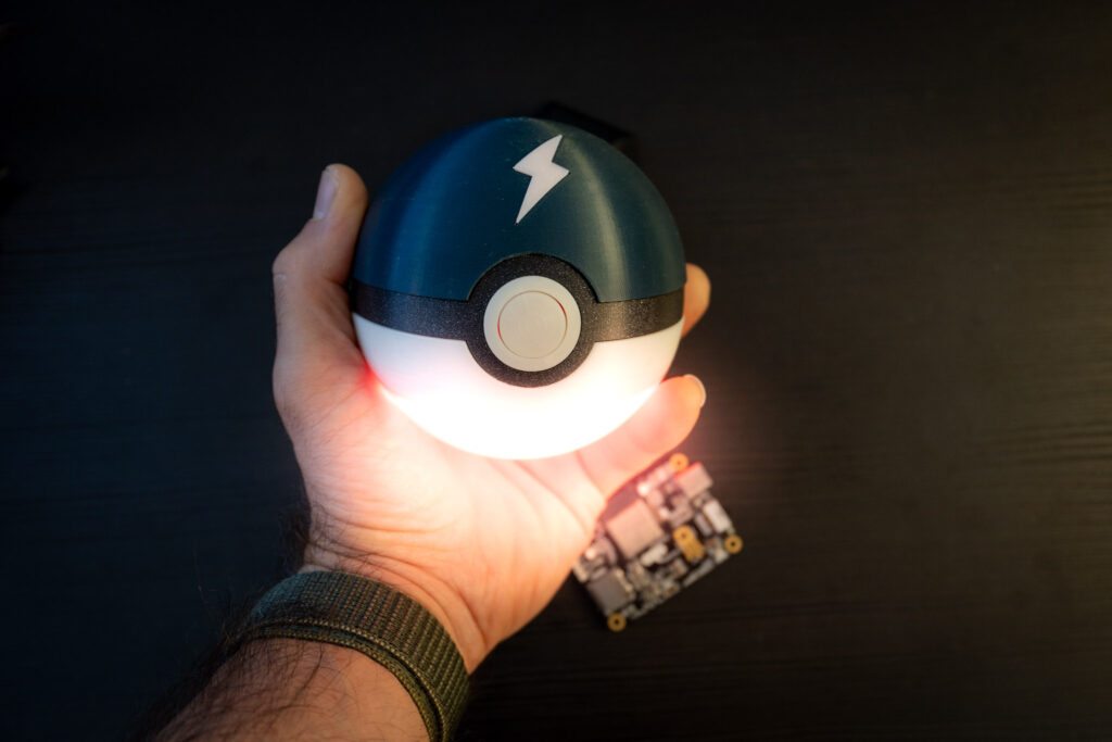
In this project, I’m using an ESP32S3 microcontroller to remotely control an LED ring housed inside a custom-built Pokéball. The setup is adaptable, so while I’m transforming a static Pokéball into something interactive, the same principles could be used to control nearly any other device or sensor.
The full code for this project will be released after all the parts are posted on my blog, and you’ll find it on my GitHub.
The hardware itself is simple—just a few key components, including the ESP32S3, an addressable RGB LED ring, and a 3D-printed shell. But the real challenge and excitement come from the software. I’ll be building a web app for user control, setting up a WebSocket connection for real-time interaction, and configuring the ESP32S3 as a server access point so it can serve the web app files directly from its internal flash storage.
This project is a great way to learn about embedded software development, network configuration, and using web interfaces to control physical devices. My aim is to not only create an interactive Pokéball but also to dive deep into these technical skills, making this project both fun and informative. Whether you’re interested in IoT or just looking to expand your embedded development skills, I think this project will offer a unique mix of hands-on experience and technical insights.
Essential Hardware: Components Needed to Build the Controller
I’m using my custom OCTO S3 development board for this project. It’s based on the ESP32-S3 microcontroller and includes several useful components, like onboard RGB LEDs, a push button, expansion connectors on the bottom side, an SD card reader, power management, battery management, and a USB-C connector. This board allows for battery operation, which is a particularly cool feature for this project, as it adds portability and flexibility.
For this setup, any ESP32-S3 development board could work, but I chose the OCTO S3 for its built-in features that simplify development. For instance, the onboard RGB LEDs and pushbutton can make debug easier, the SD card reader can be useful for future expansions and the battery management system makes it easy to keep everything powered without needing to be connected to a power cable.
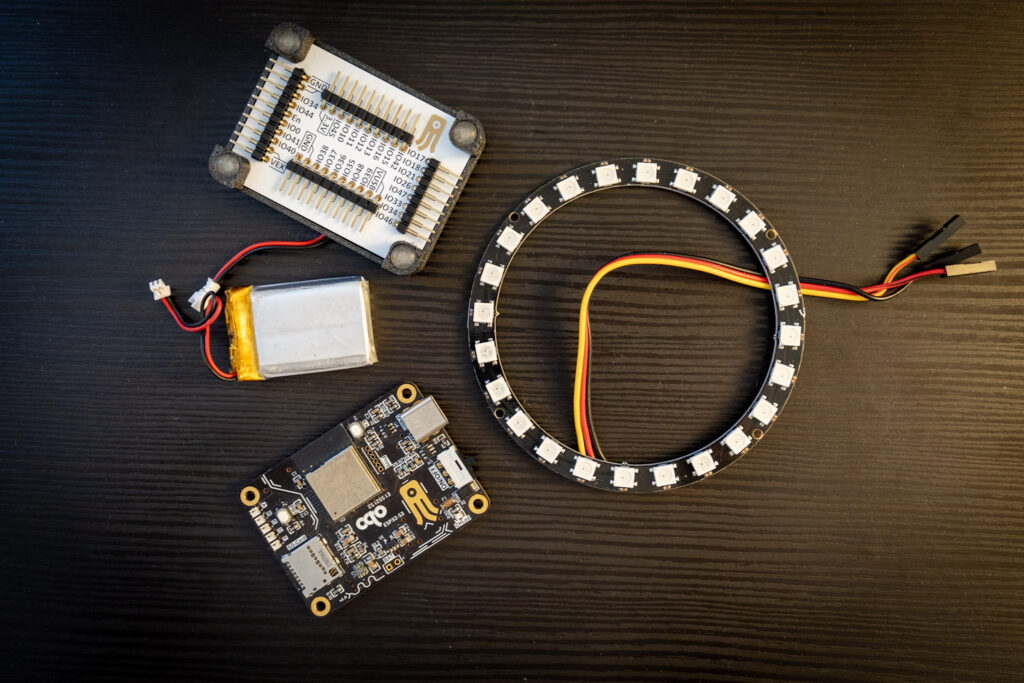
In the image below, I’ve laid out the essential components needed to get started:
- ESP32-S3 Development Board – the microcontroller that handles Wi-Fi connectivity, LED control, and web communication.
- Battery – for portable power, allowing me to operate the device wirelessly.
- LED Ring – to create the visual effects controlled by the ESP32.
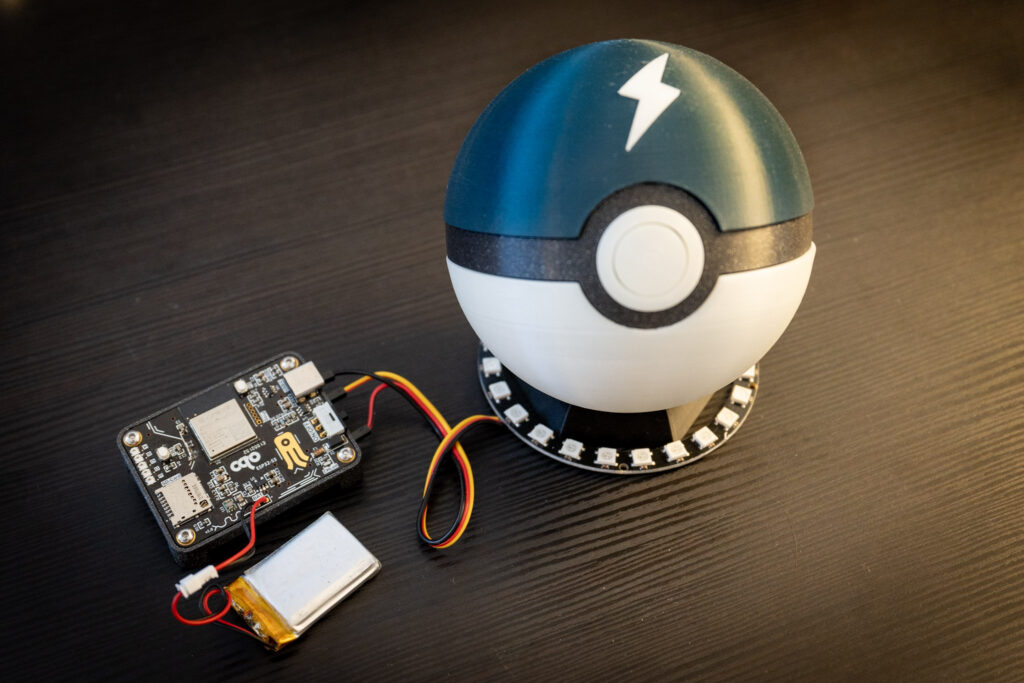
- Pokéball – which houses all components, turning this into a functional yet fun interactive object.
These components form the core of the project, and I’ll be adding more capabilities as we progress.
Technical Foundations: Wi-Fi, AP Mode, and Communication
In this project, I’m diving into a range of Wi-Fi and network-related concepts, so having at least a basic understanding of these topics will be helpful. The ESP32-S3 is a powerful microcontroller with advanced Wi-Fi capabilities, and here, I’ll be configuring it to act as both a station access point and a server. This allows it to serve up a web app (comprising HTML, CSS, and JavaScript files) directly to a connected device, like a smartphone.
Here’s how it works: the ESP32 will create a local access point with a unique SSID and password. By connecting my smartphone to this network, I can then open a web browser and access a specific IP address hosted by the ESP32. This IP serves as the entry point to request and view the web app stored on the ESP32’s flash memory.
To enable real-time interaction between the smartphone and the ESP32, I’ll be using WebSocket communication. A WebSocket is a protocol that establishes a continuous, two-way connection between the client (in this case, the smartphone) and the server (the ESP32S3). Unlike traditional HTTP requests, where a client sends a request and waits for a single response, WebSocket enables ongoing data exchange. This is essential for interactive control, as it lets the smartphone send commands (such as color changes or LED patterns) instantly, and the ESP32 can respond in real time without needing to refresh the page.
In summary, this setup lets me control the ESP32 in real-time over a direct Wi-Fi connection—essentially transforming the Pokéball into an interactive, wireless device.
Leveraging ESP32S3’s Flash Memory for File Storage
The ESP32-S3 comes in various configurations for internal flash memory, and for this project, I’m using a model with 4MB of internal flash. This memory will hold both the firmware and the web app files. To store and serve the web app efficiently, I’ll set aside a portion of the flash specifically for file storage, which will allow me to upload the necessary HTML, CSS, and JavaScript files alongside the firmware.
To accomplish this, I’m leveraging SPIFFS (SPI Flash File System), a file system designed for microcontrollers with limited memory resources. SPIFFS allows the ESP32 to emulate a small file system within its flash, where I can upload and store the web app files. This setup lets me allocate, for example, 1MB of the flash exclusively for these files.
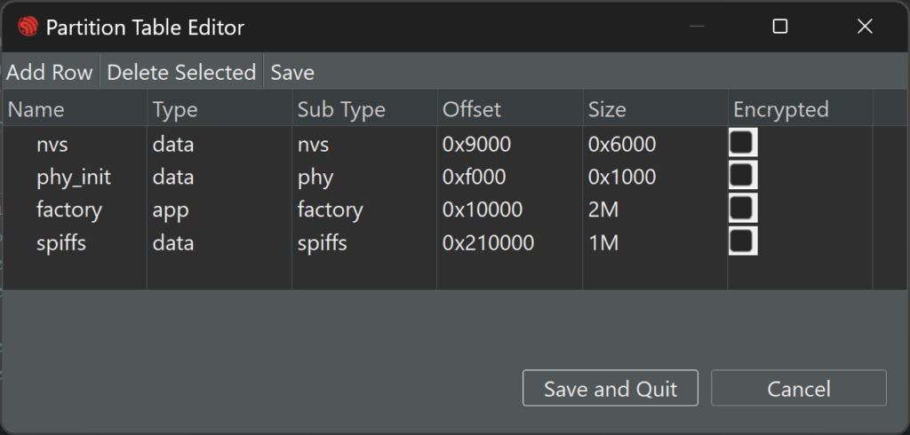
To make this work, I’ll adjust the partition table, a configuration that specifies how the ESP32’s flash memory is divided among the firmware, file storage, and other essential sections. By reserving dedicated space for SPIFFS in the partition table, I ensure there’s enough room for both the firmware and the web app.
Once the files are stored on the ESP32S3, the next step is handling client requests to serve them. Using a specific HTTP send function, the ESP32 can respond to a client’s request by delivering the appropriate file (such as the HTML file for the user interface). I’ll walk through each of these steps to set up file storage and configure the ESP32 to serve the files efficiently.
Configuring the ESP32: Setup and Initial Firmware
To get this project up and running, I’m using ESP-IDF, the official development framework for the ESP32 from Espressif (Link here). A great starting point is Espressif’s SoftAP example, which demonstrates how to set up the ESP32S3 as an access point (AP) for other devices to connect to. This example forms the foundation for the project, as it allows us to build on top of it by adding the web server, RGB control, custom partitioning, SPIFFS configuration, and more.
The first step is configuring the sdkconfig file to meet our project’s needs. Here’s a list of the key configurations I needed to adjust before getting started:
- Custom partition table to allocate flash space for firmware and file storage
- FreeRTOS tick rate set to 1kHz for precise timing
- CPU clock frequency at 240MHz for optimal performance
- WebSocket transport enabled to support two-way communication
- Internal flash size set to 4MB
- Wi-Fi settings including SSID and password for the access point
Next, I create a custom partition table with 1MB allocated specifically for SPIFFS, ensuring there’s dedicated space for the web app files. Then, I create a folder named front to store the web files (index.html, styles.css, and script.js). These files are empty for now but will hold the web app content as we build it out.
To make sure the ESP32 recognizes and includes these files during the build, I update the CMakeLists.txt file with the following line to embed them into the firmware:
EMBED_FILES "${CMAKE_CURRENT_SOURCE_DIR}/../front/index.html" "${CMAKE_CURRENT_SOURCE_DIR}/../front/styles.css" "${CMAKE_CURRENT_SOURCE_DIR}/../front/script.js"Once everything is set up and compiled, I can see my ESP32S3 network listed when I scan for available Wi-Fi networks on my phone, and I’m able to connect to it directly. This confirms that the ESP32 is successfully configured as an access point, ready to serve the web app and respond to commands for controlling the LED ring.
Add RGB LED controll
Before closing the first part of this series on controlling the ESP32-S3 with a web interface, let’s add RGB LED control. First, we need to install the LED driver component in our project. In ESP-IDF, right-click on the project, select “Install New Component,” and add led_strip. Next, include the component at the top of main.c with #include "led_strip.h".
At this point, we can create a function to initialize the LED strip. Here’s the code:
//Struct for RGB LED colors
typedef struct{
    uint8_t R_color;
    uint8_t G_color;
    uint8_t B_color;
}t_rgb_color;#define RGB_LEDS_DI_BOTTOM 44
led_strip_handle_t led_strip_bottom;

static void configure_led(void){
    /* LED strip initialization with the GPIO and pixels number*/
    led_strip_config_t strip_config= {
        .strip_gpio_num = RGB_LEDS_DI_BOTTOM,
        .max_leds = 24, // at least one LED on board
    };
    led_strip_rmt_config_t rtm_config= {
        .resolution_hz = 10 * 1000 * 1000, // 10MHz
    };
    ESP_ERROR_CHECK(led_strip_new_rmt_device(&strip_config, &rtm_config, &led_strip_bottom));
    /* Set all LED off to clear all pixels */
    led_strip_clear(led_strip_bottom);
}
To control the LED colors, we can use functions like led_strip_clear, led_strip_set_pixel, and led_strip_refresh, which allow us to control individual LEDs, change colors, turn LEDs on or off, or clear the entire strip.
Now, let’s add a feature to detect if a device is connected to our access point and change the LED color accordingly. We can define a boolean flag to track connection status, setting it to true or false depending on connection or disconnection events. In wifi_init_softap, there’s a function, esp_event_handler_instance_register, that registers a handler, wifi_event_handler, which will be triggered on Wi-Fi events. In the handler, we can use an if condition to detect connection or disconnection events, as shown here:
static void wifi_event_handler(void* arg, esp_event_base_t event_base,
                                    int32_t event_id, void* event_data)
{
    if(event_id == WIFI_EVENT_AP_STACONNECTED) {
        wifi_event_ap_staconnected_t* event= (wifi_event_ap_staconnected_t*) event_data;
        ESP_LOGI(TAG, "station "MACSTR" join, AID=%d",
        MAC2STR(event->mac), event->aid);
        pokeball_connected = true;
    } else if(event_id == WIFI_EVENT_AP_STADISCONNECTED) {
        wifi_event_ap_stadisconnected_t* event= (wifi_event_ap_stadisconnected_t*) event_data;
        ESP_LOGI(TAG, "station "MACSTR" leave, AID=%d",
        MAC2STR(event->mac), event->aid);
        pokeball_connected = false;
    }
}
Finally, in the main loop (while(1)), we can check the flag. If true, the LED color is set to white; if false, it turns red.
while(1){
   if(pokeball_connected == false){
      led_color.B_color = 0;
      led_color.G_color = 0;
      led_color.R_color = 75;
      rotate_pixels(led_strip_bottom, 24, led_color);
   }else{
      led_color.B_color = 75;
      led_color.G_color = 75;
      led_color.R_color = 75;
      rotate_pixels(led_strip_bottom, 24, led_color);
   }
vTaskDelay(pdMS_TO_TICKS(500));
}
Part 2 Preview
We’re now ready to take things to the next level. In the next article, we’ll set up the server so that the ESP32-S3 can serve the web app directly to a connected client. We’ll also create a basic web app to view directly on our phone. Stay tuned for Part 2!
Thank you for reading and supporting my blog! If you enjoyed this content and would like to help me continue creating more, please consider leaving a donation. Your generosity will help me cover the costs of materials and tools for future projects. Any amount is greatly appreciated! And remember to follow me on Instagram for more updates and behind-the-scenes content.

