Welcome to the third part of our mini thermal camera project! So far, we’ve set up the hardware and configured LVGL for our ESP32-S3 microcontroller. If you missed any steps, be sure to check out Part 1 and Part 2.
In this segment, I’ll detail the creation and configuration of the graphical elements needed for the thermal camera. Following this, we’ll integrate the thermal sensor readings and display them using our graphical interface. By the end of this tutorial, you’ll have a functional thermal camera capable of capturing and displaying real-time thermal images. Let’s get started!
Creating Essential UI Elements for the Thermal Camera

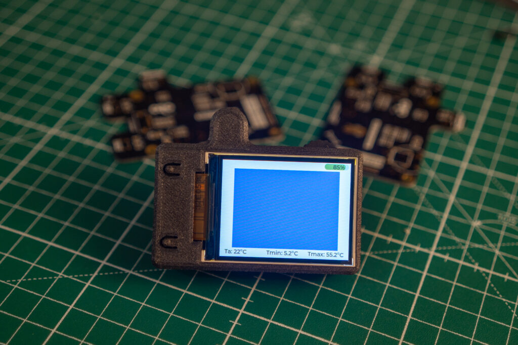
In this part, we are going to create and configure essential graphical elements for the user interface. First, we’ll create labels for ambient temperature, maximum temperature, and minimum temperature using the lv_label_create function. These labels will be positioned at the bottom of the screen with the lv_obj_align function.
/*Create label for ambient temperature visualization*/
label_ta = lv_label_create(lv_scr_act());
lv_label_set_text(label_ta , "Ta: 22°C");
lv_obj_align(label_ta , LV_ALIGN_BOTTOM_LEFT, 12, -4);

/*Create label for maximum temperature visualization*/
label_tmax = lv_label_create(lv_scr_act());
lv_label_set_text(label_tmax , "Tmax: 55.2°C");
lv_obj_align(label_tmax , LV_ALIGN_BOTTOM_RIGHT, -12, -4);

/*Create label for minimum temperature visualization*/
label_tmin = lv_label_create(lv_scr_act());
lv_label_set_text(label_tmin , "Tmin: 5.2°C");
lv_obj_align(label_tmin , LV_ALIGN_BOTTOM_MID, -5, -4);
Next, we’ll create a battery indicator using a bar element with lv_bar_create. This bar will be styled to change color based on the battery level, displaying green when battery is full and red when low, in particular I want the color gradient to start when the charge goes below 65%.
/*Create battery indicator*/
static lv_style_t style_indic;
lv_style_init(&style_indic);
lv_style_set_bg_opa(&style_indic, LV_OPA_COVER);
lv_style_set_bg_color(&style_indic, lv_palette_main(LV_PALETTE_LIGHT_GREEN));

bar = lv_bar_create(lv_scr_act());
lv_obj_set_size(bar , 60, 15);
lv_obj_align(bar ,LV_ALIGN_TOP_RIGHT,-5,2);
lv_bar_set_value(bar , 85, LV_ANIM_ON);
lv_obj_add_style(bar , &style_indic, LV_PART_INDICATOR);

label_bat = lv_label_create(lv_scr_act());
lv_label_set_text(label_bat , "85%");
lv_obj_align(label_bat , LV_ALIGN_TOP_RIGHT, -15, 2);

if(battery_lev < 60){
     lv_style_set_bg_color(&style_indic, lv_palette_main(LV_PALETTE_ORANGE));
     lv_style_set_bg_grad_color(&style_indic, lv_palette_main(LV_PALETTE_LIGHT_GREEN));
     lv_style_set_bg_grad_dir(&style_indic, LV_GRAD_DIR_HOR);
     lv_obj_report_style_change(&style_indic);
}else if(battery_lev > 65){
     lv_style_set_bg_color(&style_indic, lv_palette_main(LV_PALETTE_LIGHT_GREEN));
     lv_style_set_bg_grad_dir(&style_indic, LV_GRAD_DIR_NONE);
     lv_obj_report_style_change(&style_indic);
}
We will also create a graphical object for thermal image visualization using the lv_img_create function. The source of the image, set by the lv_img_set_src function, is a buffer containing the image data. This buffer will be detailed later when we discuss the IR array sensor. The thermal image will be centered on the screen and zoomed in, as the infrared array is small compared to the screen size.
/* Create image buffer for IR array visualization, the array size is 2 times the size of sensor array */
img_ir = malloc(SENS_H*SENS_V*2);
for (int b_idx = 0; b_idx< SENS_H*SENS_V; b_idx++){
   img_ir [b_idx*2] = 0xFF;  //Fill it in Blue
   img_ir [b_idx*2+1] = 0;
}

/* Initialize png to contain the image buffer */
my_png.header.w = SENS_V;
my_png.header.h = SENS_H;
my_png.data_size = SENS_V * SENS_H * 2;
my_png.header.cf = LV_COLOR_FORMAT_RGB565;
my_png.data = img_ir ;

/* Create graphical object fo thermal image visualization */
lv_obj_t * img1 = lv_img_create(lv_scr_act());
lv_img_set_src(img1 , &my_png);
lv_obj_remove_style_all(img1 );
lv_obj_align(img1 , LV_ALIGN_CENTER, 2, 0);
lv_obj_set_size(img1 , SENS_V, SENS_H);
lv_img_set_antialias(img1 , 1);
lv_img_set_zoom(img1 , 256 * 4.1);
Integrating the MLX90640 Sensor: Firmware and Implementation
In this section, we’ll dive into the integration of the MLX90640 sensor, focusing on the firmware required to interface with the sensor. While the sensor’s specifications were covered in the first part of the tutorial, here we’ll explore how to set up the firmware to read data from the sensor and process it for our thermal camera application. This includes configuring communication protocols, handling sensor data, and preparing the thermal image buffer for display on the screen.
I started with the libraries provided by Melexis, which are available on their dedicated GitHub page. These libraries needed adaptation for the ESP32-S3 microcontroller. Specifically, I integrated the driver with the I2C-specific code and made minor adjustments to the API, including adding some defines. The complete code for the thermal camera project is available on my GitHub repository, Link at the end of this post.
To use the device, you need to:
- Define data sets and buffers for data storage.
- Call
MLX90640_I2CInit(). - Set the data rate.
- Read the EEPROM.
- Extract parameters.
- Start getting the data frame.
The API also includes functions to convert raw data to temperature and store everything in a buffer.
MLX90640_I2CInit();
MLX90640_SetRefreshRate(MLX90640_I2C_ADD,MLX90640_REFRESH_RATE_16HZ);
status = MLX90640_DumpEE (MLX90640_I2C_ADD, eeMLX90640);
if(status != ESP_OK){
      ESP_LOGI(TAG, "Error in reading MLX90640_DumpEE");
}
status  = MLX90640_ExtractParameters(eeMLX90640, &mlx90640);
if(status != ESP_OK){
      ESP_LOGI(TAG, "Error in reading MLX90640_ExtractParameters");
}
if(MLX90640_GetFrameData(MLX90640_I2C_ADD, mlx90640Frame) >= 0){
      tir_amb= MLX90640_GetTa(mlx90640Frame, &mlx90640) - TA_SHIFT;
      MLX90640_CalculateTo(mlx90640Frame, &mlx90640, EMISSIVITY, tir_amb, mlx90640To);
      /* mlx90640To contains the array of temperatures */
}
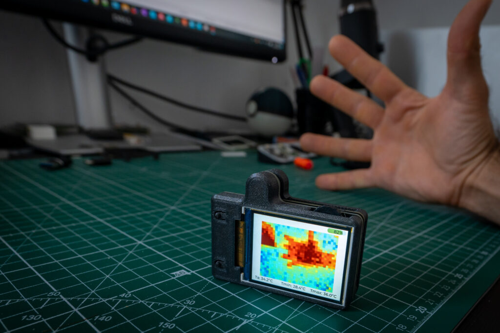
At this point, you need to extract information from the temperature buffer, such as minimum and maximum values, and convert temperatures to colors. I used the “jet” color map for visualizing the temperature. The “jet” color map transitions from blue (for low values) through cyan, green, yellow, and red (for high values), providing a clear gradient for temperature representation. Below is the implementation of the conversion function. It first normalizes the temperature value to a range between 0 and 1 based on the provided minimum and maximum temperatures. This ensures that the temperature value is scaled appropriately for color mapping. The final color is then mapped based on predefined thresholds. The minimum and maximum temperatures also determine the dynamic range of the image; they dictate the range of temperatures that can be visualized. In my example, min_temp and max_temp are set statically in the code, but they can also be adjusted dynamically based on actual measurements.
/* Function to map temperature to color using the Jet colormap */
void temp_to_jet_color(float temp, float min_temp, float max_temp, uint8_t *r, uint8_t *g, uint8_t *b) {

    float norm_temp = (temp- min_temp) / (max_temp- min_temp);
    norm_temp = fmin(fmax(norm_temp , 0.0), 1.0); // Clamp value between 0 and 1

    if(norm_temp < 0.125) {
        *r = 0;
        *g = 0;
        *b = (uint8_t )(128 + 127 * norm_temp / 0.125);
    } else if(norm_temp < 0.375) {
        *r = 0;
        *g = (uint8_t )(255 * (norm_temp - 0.125) / 0.25);
        *b = 255;
    } else if(norm_temp  < 0.625) {
        *r = (uint8_t )(255 * (norm_temp - 0.375) / 0.25);
        *g = 255;
        *b = (uint8_t )(255 - 255 * (norm_temp - 0.375) / 0.25);
    } else if(norm_temp < 0.875) {
        *r = 255;
        *g = (uint8_t )(255 - 255 * (norm_temp  - 0.625) / 0.25);
        *b = 0;
    } else {
        *r  = (uint8_t )(255 - 128 * (norm_temp - 0.875) / 0.125);
        *g = 0;
        *b = 0;
    }
}
Because the screen size is much larger than the infrared array sensor size, I decided not only to zoom the image using LVGL functions but also to enlarge the thermal array to four times the actual size of the sensor. I defined SENS_H as 2*24 and SENS_V as 2*32, so when copying the thermal image into the buffer, a single IR pixel is copied into four image pixels. I did this because excessive zooming with LVGL functions introduced too many artifacts, and this method provides better visualization.
/* Map the thermal image */
for (int r_i = 0; r_i < SENS_H/2; r_i  ++){
     for (int h_i = 0; h_i < SENS_V/2; h_i ++){
    	t_pixel = mlx90640To[(SENS_V/2 - 1 - h_i) + r_i * SENS_V/2];
    	/* Set min and max for the colored image dinamic range */
    	t_d_min = 24;
    	t_d_max = 40;
	/* Convert temparature in colors */
       	temp_to_jet_color(t_pixel , t_d_min , t_d_max , &colo_r, &colo_g, &colo_b);
	data_t = lv_color_to_u16(lv_color_make(colo_r,colo_g,colo_b));
	/* Copy data into the image buffer*/
	img_ir[(((2*r_i )*SENS_V)+(h_i *2))*2]= (uint8_t ) data_t ;
	img_ir[(((2*r_i )*SENS_V)+(h_i *2))*2+1]= (uint8_t ) (data_t >> 8);

	img_ir[(((2*r_i )*SENS_V)+(h_i *2 + 1))*2]= (uint8_t ) data_t ;
	img_ir[(((2*r_i )*SENS_V)+(h_i *2 + 1))*2+1]= (uint8_t ) (data_t >> 8);

	img_ir[(((2*r_i +1)*SENS_V)+(h_i *2))*2]= (uint8_t ) data_t ;
	img_ir[(((2*r_i +1)*SENS_V)+(h_i *2))*2+1]= (uint8_t ) (data_t >> 8);

	img_ir[(((2*r_i +1)*SENS_V)+(h_i *2 + 1))*2]= (uint8_t ) data_t ;
	img_ir[(((2*r_i +1)*SENS_V)+(h_i *2 + 1))*2+1]= (uint8_t ) (data_t >> 8);

	}
}
Conclusion
In this part of the tutorial, we successfully created essential UI elements for our thermal camera and integrated the MLX90640 sensor, focusing on the firmware and implementation. By enhancing the user interface and properly scaling the thermal image, we ensured a decent visualization on our display.
To access to the full code, visit my GitHub repository. This repository contains all the resources and code needed to build and refine your own mini thermal camera. You will notice that the operations for UI updates and thermal image buffer writing are managed by a semaphore to prevent the overlap of writing and reading operations. This ensures that data integrity is maintained by allowing only one process to access the shared resources at a time, thus avoiding potential conflicts and ensuring smooth and efficient operation of the thermal camera system. Happy coding!

Thank you for reading and supporting my blog! If you enjoyed this content and would like to help me continue creating more, please consider leaving a donation. Your generosity will help me cover the costs of materials and tools for future projects. Any amount is greatly appreciated! And remember to follow me on Instagram for more updates and behind-the-scenes content.

