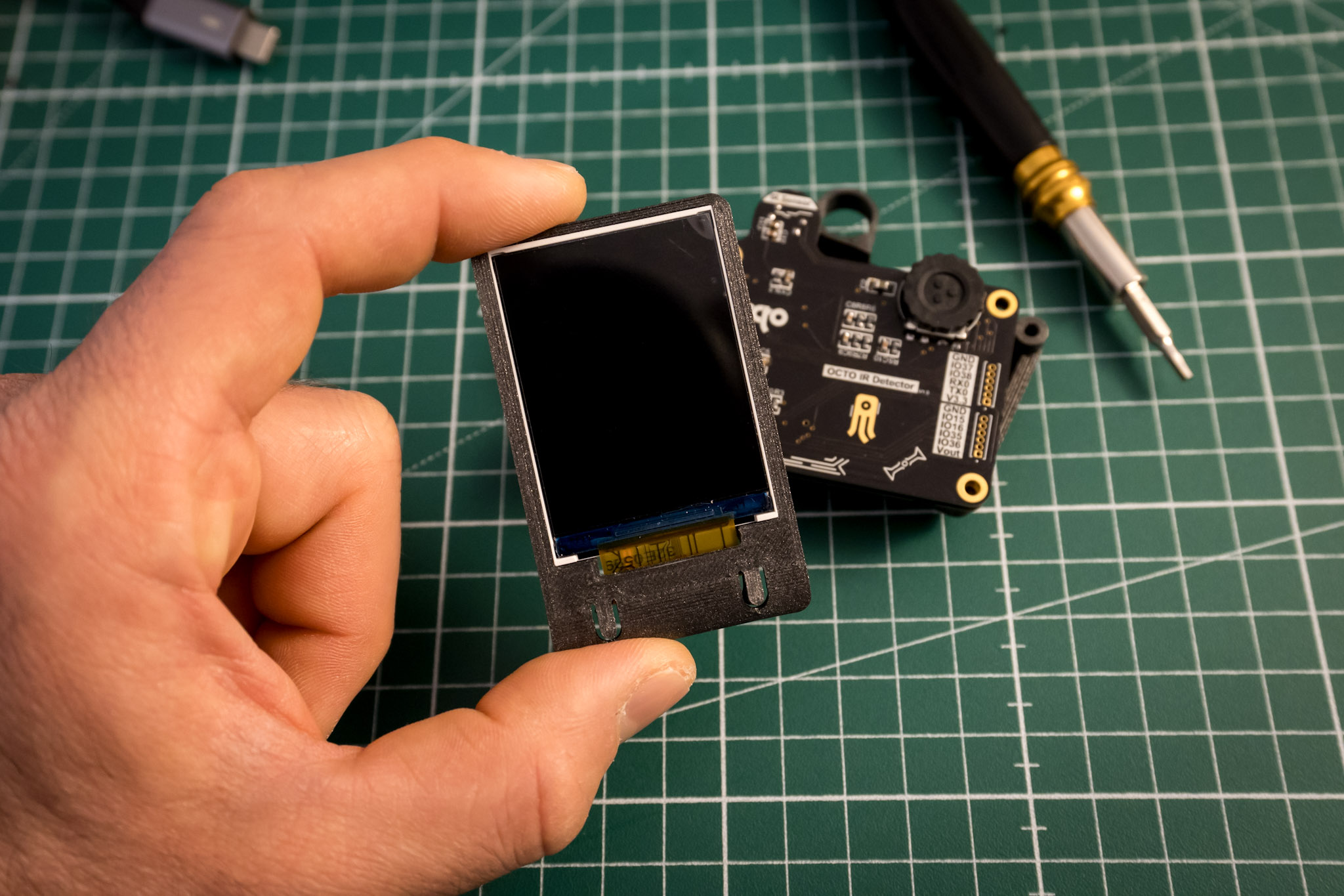
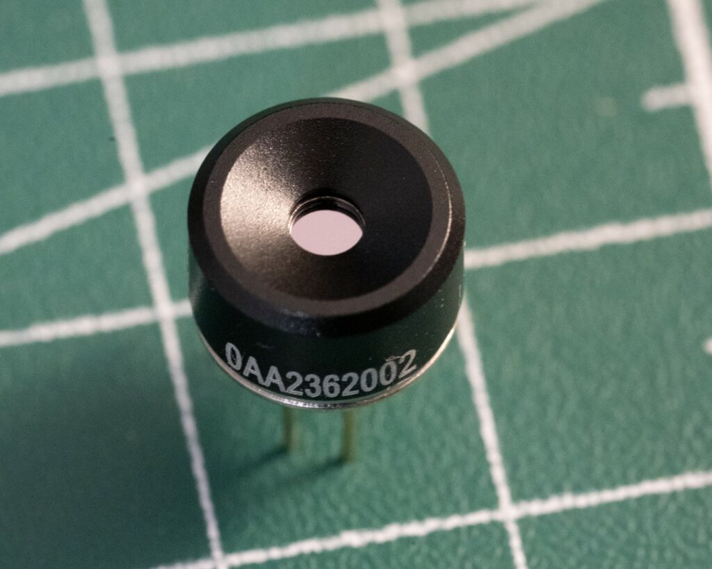
Lately I came across a component I never used before, the MLX90640.
It’s a compact thermal camera module that uses an array of 32×24 infrared (IR) sensors to capture thermal images. It measures surface temperatures accurately and produces thermal images in real-time, making it ideal for various applications such as human detection, industrial inspection, and thermal monitoring. The module supports a wide temperature range, and its small size and ease of integration make it suitable for portable and embedded systems. It communicates via I2C, allowing for straightforward interfacing with microcontrollers and other devices.
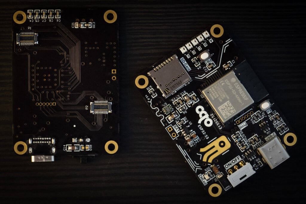
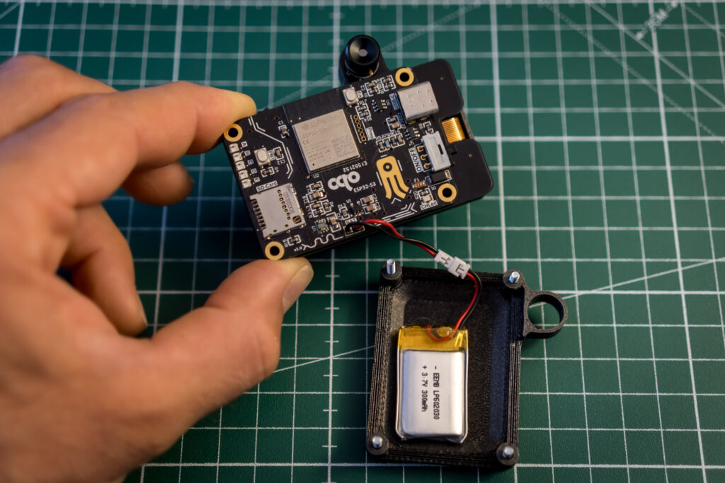
The MLX90640 immediately caught my attention, so I decided to build something with it: a thermal camera. I have a custom microcontroller board that I built, which I might talk about more in another post. It’s based on an ESP32-S3, has a micro SD card slot, works on battery, and includes a couple of slim stack connectors for easy expansion. You can see it in the picture below. This makes it perfect for building child boards to extend functionality. So, I decided to create a child board to make a thermal camera.
Application Scenarios
This thermal camera can be used for a variety of applications. Here some examples:
Home Inspections: identifying heat leaks, poor insulation, and potential electrical issues in your home. By visualizing temperature variations, you can pinpoint areas that need attention, ultimately improving energy efficiency and safety.
Electronics Troubleshooting: Overheating components can be a sign of malfunction in electronic devices. Using the thermal camera, you can easily detect hotspots on PCBs and other electronic assemblies, aiding in rapid diagnostics and repair. But also to check if your prototype is behaving as expected.
Environmental Monitoring: Track temperature changes in various environments, whether it’s monitoring wildlife habitats, agricultural fields, or urban areas. One of the most interesting applications I found was during a visit to a geothermal area in Tuscany, where I could spot heat variations with the camera. Check out this video I made about it. This camera can provide valuable data for environmental studies.
Monitoring and Maintenance: This thermal camera can be used to monitor machinery, detect overheating parts, and prevent failures before they cause significant downtime or damage.
Potential Disadvantages
Reflectivity of Materials: The accuracy of the IR sensor can be affected by the reflectivity of materials. Certain surfaces, especially shiny metals, can reflect infrared radiation, leading to inaccurate readings.
Ambient Temperature: The sensor’s performance can be influenced by the surrounding temperature. In very hot or very cold environments, the sensor might not provide accurate readings.
Field of View: The MLX90640 has a fixed field of view, which might not be suitable for all applications. It is produced in two alternatives: 55°x35° and 110°x75°and I got the wide angle one.
Resolution and Frame Rate: While the MLX90640 provides a decent resolution for many applications, it might not be sufficient for high-precision requirements. Additionally, its frame rate is limited, which can affect the ability to capture fast-moving objects.
Designing flow
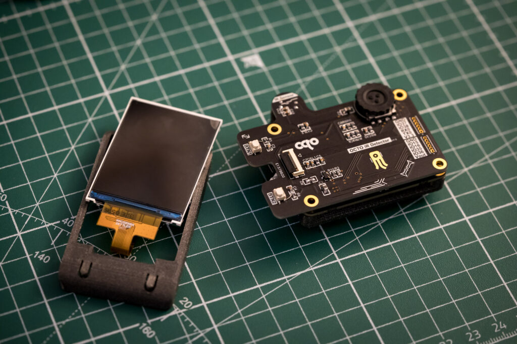
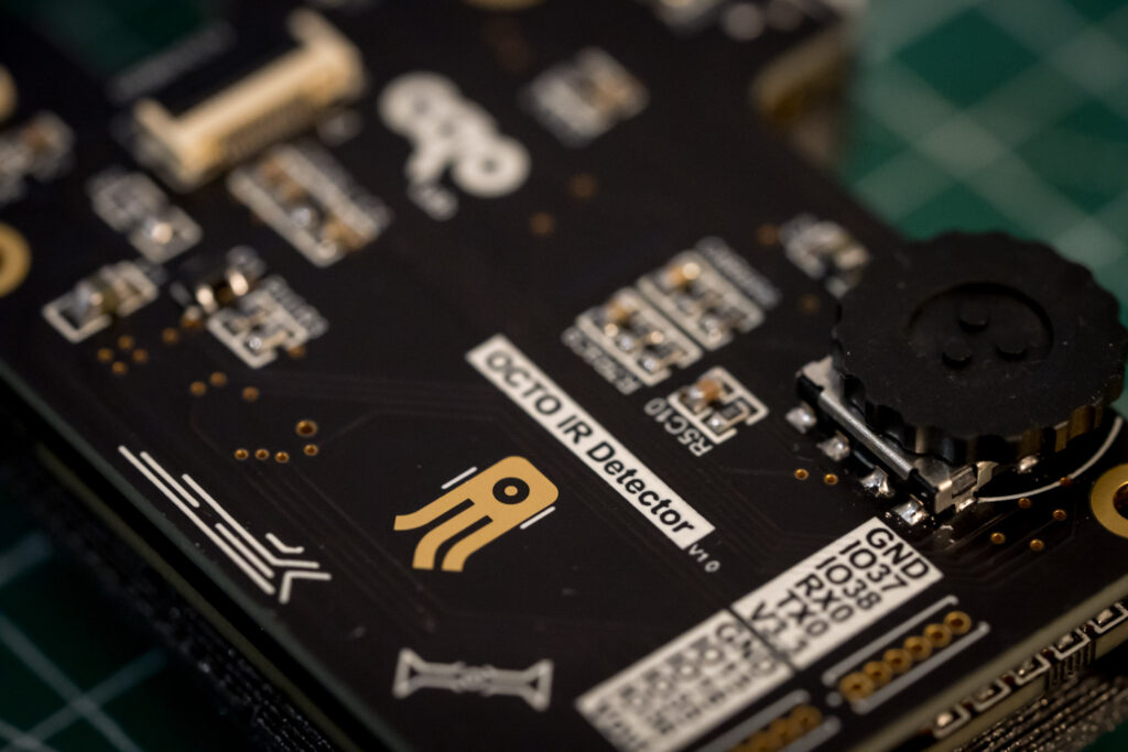
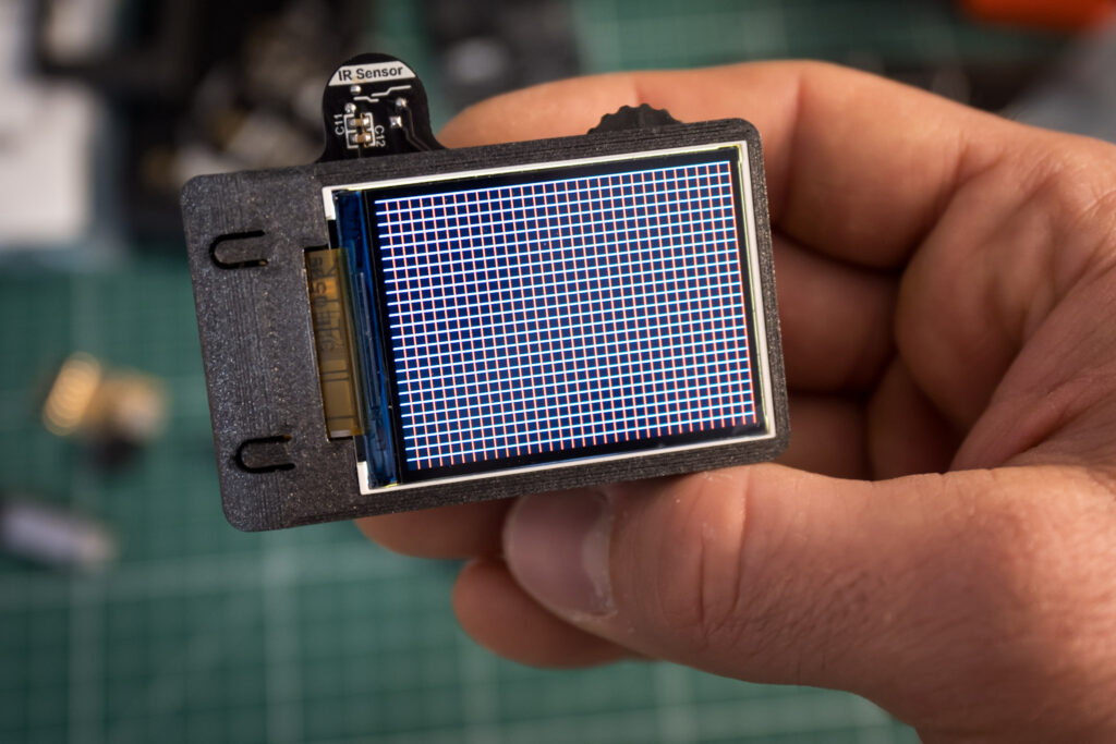
The thermal camera shield is very simple but has everything to look like a real camera. It includes a couple of pushbuttons, a slim rotary encoder wheel (which also has a button to take pictures), an SPI color display, and, of course, the image sensor, which is the infrared array.
To make this project real, I need to work on both hardware and firmware. In this Part 1, I’ll talk about the hardware. So let’s see how to interface the main character of this project with the ESP32-S3.
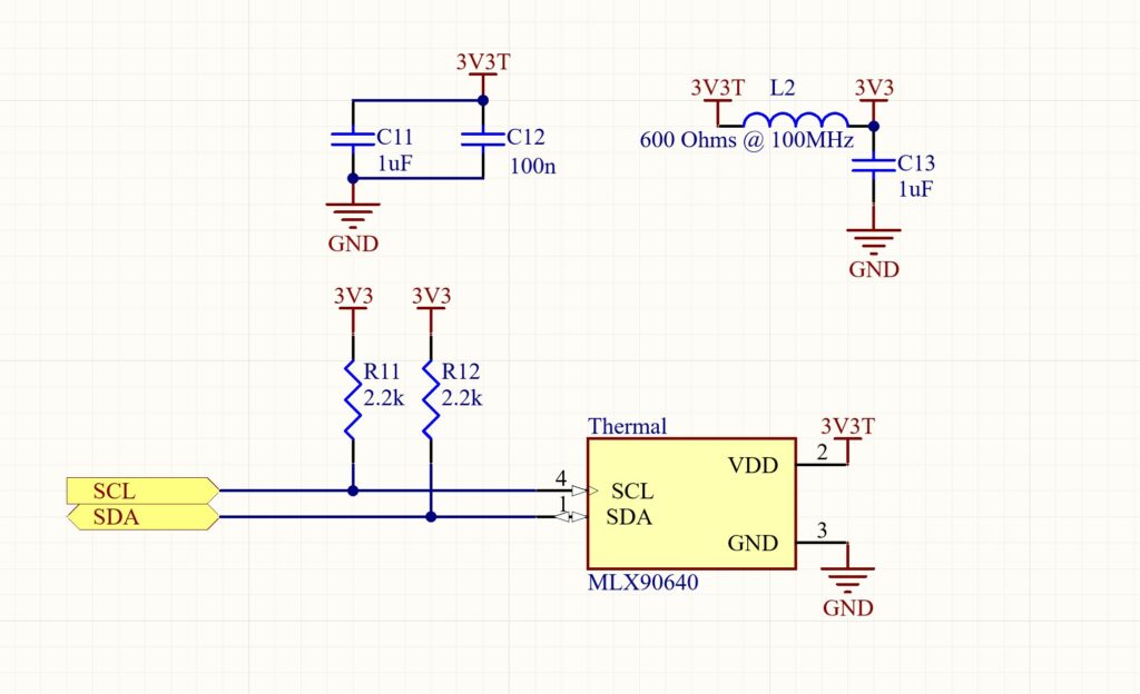
The MLX90640 sensor interfaces with the microcontroller via I2C, a communication protocol that uses two wires: SDA (data line) and SCL (clock line). By connecting these lines from the sensor to the corresponding pins on the ESP32-S3, we can easily transmit thermal data for processing and display.
The 3.3V power supply comes from the microcontroller board so I also placed a ferrite bead on power supply in conjunction with decoupling capacitors. It is a good method to improve the power supply quality for sensitive components like the MLX90640, especially when using switching power supplies like in my case. This approach helps mitigate high-frequency noise and EMI.
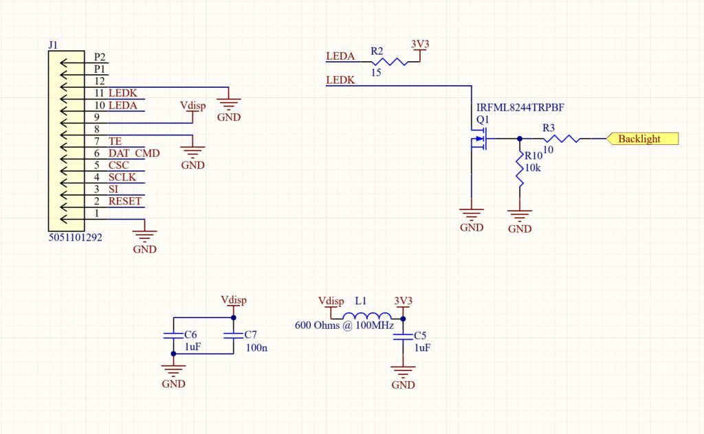
As a display, I decided to use one with a quite common controller: the ST7789v2. This popular controller supports 240 x 320 pixels, 262K colors, and features a high-speed SPI interface, partial display, and power-saving modes. It has an FPC Connector to interface with the display for which I used a 12 positions Molex 5051101292.
I’ve placed the schematics below. The backlight is driven by an N-MOSFET. To get the value for the LED resistor, we need to check the datasheet. Given a power supply of 3.3V, a forward voltage of 3.0V for the LED, and a desired current of 20mA:
![]()
So, a 15Ω resistor would be appropriate for the backlight.
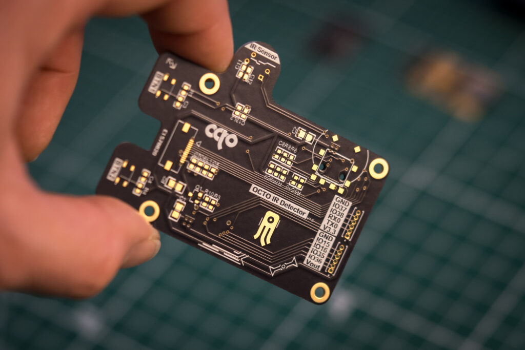
After completing the schematics, I started designing the PCB. As I mentioned, I want it to look like a camera, so I placed the sensor on the top left and the wheel for taking pictures on the top right. The display will be positioned in the middle of the board, with a couple of buttons on the left.
I also placed a couple of expansion connectors because you never know when they might be useful. There are some mounting holes and slim stack connectors on the backside to attach it to the microcontroller board. It’s a very simple board, two layers are enough. Below, I’ve included some pictures of it.
Part 2 preview
In the second part of the project, we’ll dive into the firmware development for our thermal camera. The firmware will involve using the C sensor library to interface with the MLX90640 sensor and the LVGL (Light and Versatile Graphics Library) to display images on the LCD. We’ll cover how to set up the I2C communication, read temperature data, convert temperature readings into colors, and render the thermal images on the screen. This combination of libraries will help us create a functional and visually appealing thermal camera application. Stay tuned for a detailed walkthrough and code snippets!
Thank you for reading and supporting my blog! If you enjoyed this content and would like to help me continue creating more, please consider leaving a donation. Your generosity will help me cover the costs of materials and tools for future projects. Any amount is greatly appreciated! And remember to follow me on Instagram for more updates and behind-the-scenes content.

