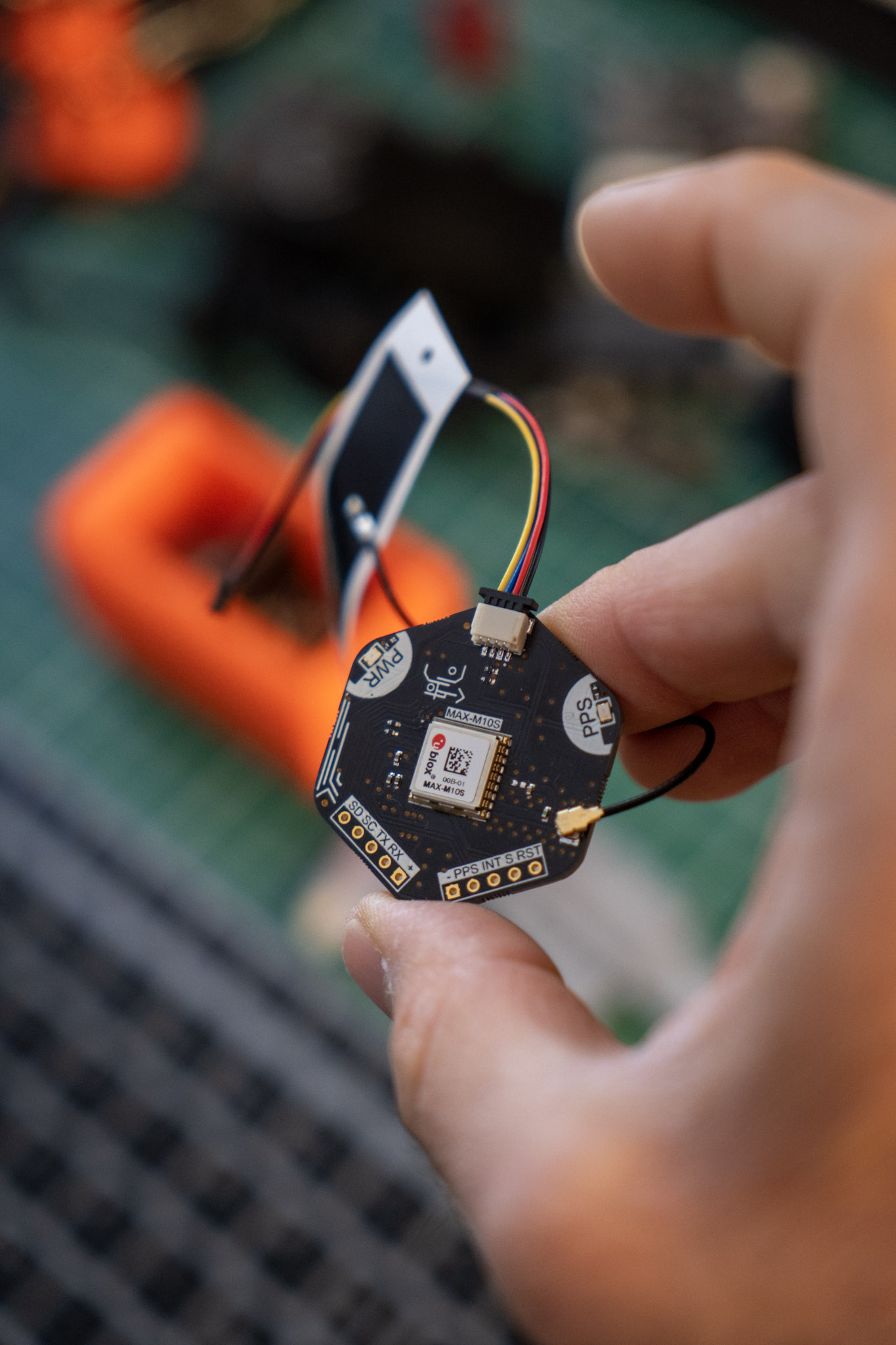
Recently, I got hooked on satellite positioning systems and tested a few modules and evaluation boards available on the market. I also built a GPS tracker that I’m really proud of, but maybe I’ll write about that in another article. If you are curious about it, check out this video on my Instagram.
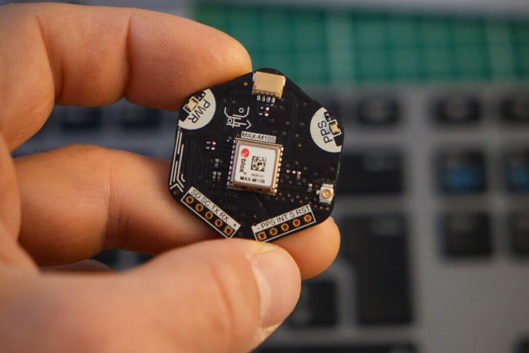
I was looking for something with good positional accuracy (around 1/1.5 meters), a small footprint, and, since I want to use it in a battery-powered device, low power consumption. After a lot of searching, I found a module that suits my application particularly well. Instead of simply buying an evaluation board, I decided to design and build one myself. In this article, I will show you how I designed and built a custom evaluation board based on the u-blox MAX-M10S global navigation satellite system.
Schematics
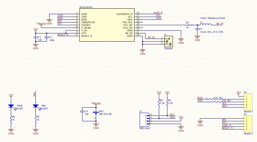
The part that certainly requires the most attention is the design of the interface with the antenna. What’s really useful for this module is an internal LNA followed by a SAW filter in the RF path.
So, what does that mean? It means that embedded into the module is a low noise amplification stage followed by a filter that allows the signal to be “cleaned” of unwanted frequencies. The result is that we can also connect passive antennas and still achieve very good performance.
For this evaluation board, I wanted to integrate the version illustrated in the “Reference designs, Typical design” section, which allows for a minimal amount of components and maintains access to the UART and I2C peripherals. The module is also equipped with an antenna supervisor, which allows you to integrate advanced functions for antenna management, but this requires more components and the I2C interface is disabled
Since I also wanted compatibility with both active and passive antennas, I included the use of the internal power supply provided on the VCC_RF pin. To connect it to the antenna, it requires an LC filter. The values of the components can be found in the manual, and you can take them from my diagram below
PCB routing
Ok, let’s move from the schematic to the PCB. One of the things I like most is designing the boards—not for the boring part of connecting the tracks, but because I can give it the look I want.
This is an important part for me: the transition from the virtual schematics to a material, physical object. It has to work well, but I also want it to look aesthetically pleasing!
Speaking about the technical part of routing, the only critical thing for this board is to make sure that the impedance of the antenna RF trace is as close to 50Ω as possible. Since my board will have two layers, the best way to draw a 50Ω trace is to have a single-coplanar configuration.
The impedance of a single-coplanar trace depends on how the PCB is actually manufactured (dielectric material characteristics, thickness, and so on), the thickness of the trace itself, and the clearance with the coplanar GND plane. There are many online tools for these calculations; PCB design software often has one built-in, or I also recommend the Saturn PCB Design Toolkit software.
After checking the PCB properties from my manufacturer and doing a bit of math, I chose to make my track 1mm wide with a gap of 0.254mm. This should be close enough to 50Ω with a deviation of less than 5%, which should be sufficient. Adding many GND vias connecting the top layer and bottom layer planes helps to improve performance as well.
I usually assemble my boards with the help of a stencil to distribute the solder paste and a hotplate to solder the components. There are hundreds of videos on YouTube if you’re interested in how to do it!
Final result
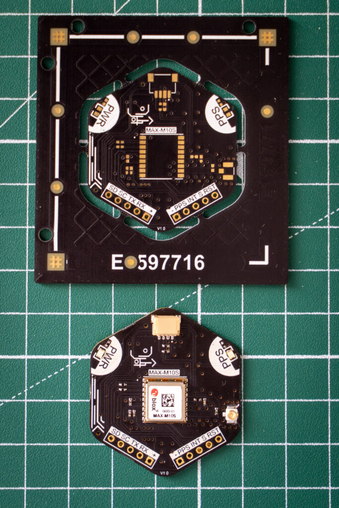
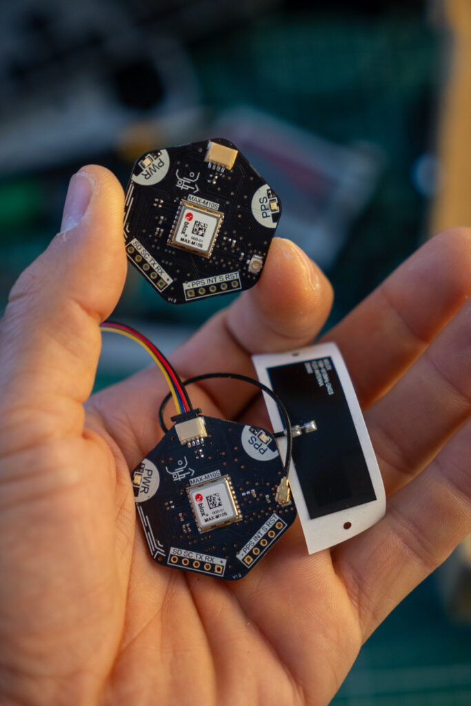
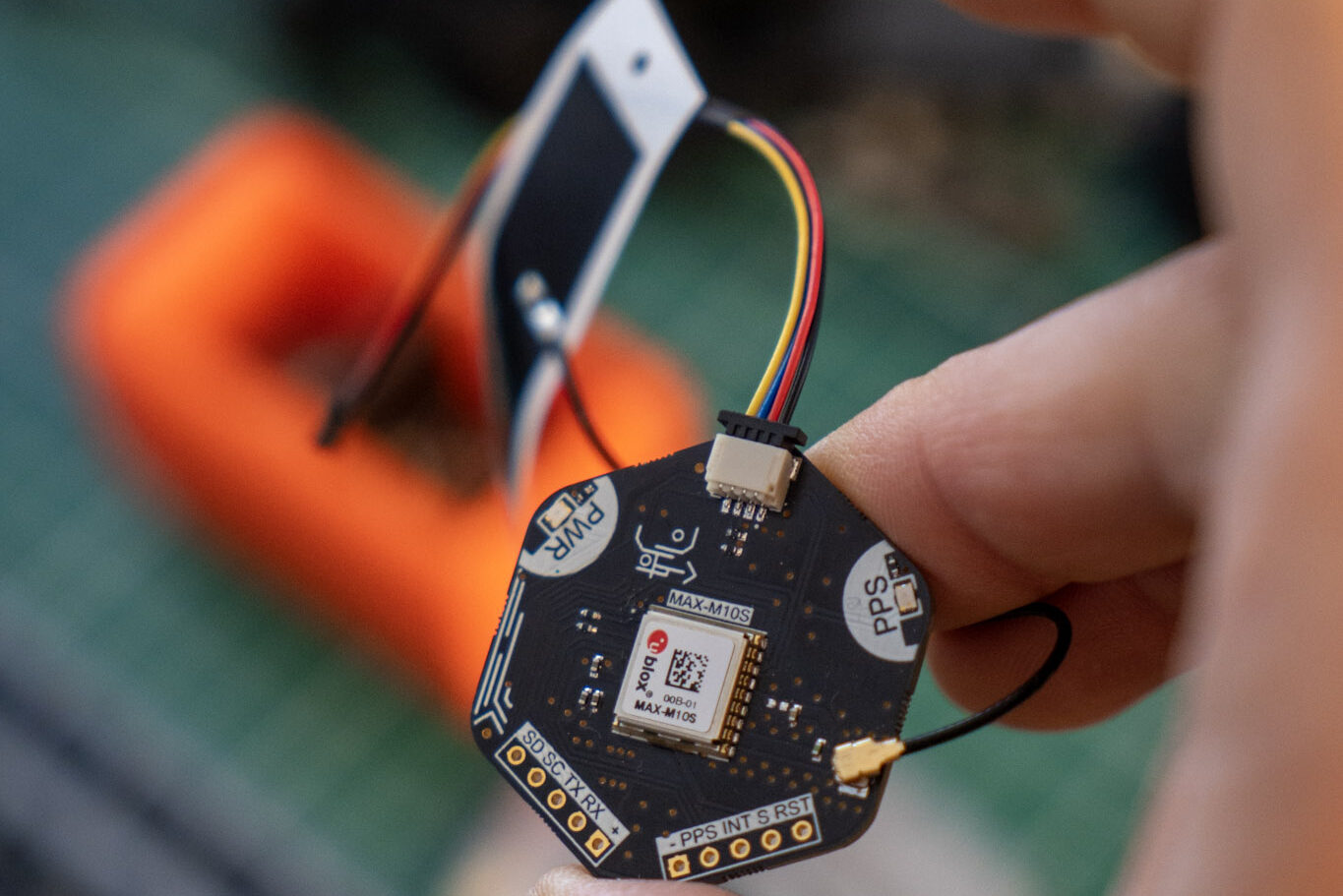
I think the result is pretty nice!
In the next post, I’ll show how to interface with this module over I2C with an ESP32-S3 microcontroller and read information about location, local time, satellites, and so on.
Thank you for reading and supporting my blog! If you enjoyed this content and would like to help me continue creating more, please consider leaving a donation. Your generosity will help me cover the costs of materials and tools for future projects. Any amount is greatly appreciated! And remember to follow me on Instagram for more updates and behind-the-scenes content.
